CATALYTIC OXIDIZER OPERATION AND VAPOR CONTROL
FALCO CATALYTIC OXIDIZER OPERATION AND VAPOR CONTROL
FALCO catalytic oxidizers have three programmable temperature controllers that respond to temperature sensors located before (T1), inside (T3), and after (T2) the catalyst. The controllers start, run, and shutdown the oxidizer based on catalyst temperature. High and low alarms shut the system down (blower and heaters) if temperatures exceed preset limits. The T1 temperature controller signals a SCR power control to rapidly cycle the heaters for precise temperature regulation. A dedicated thermocouple and high-limit controller monitor heater temperature and disconnect heater power if limits are exceeded.
Catalytic Oxidizers for Soil Vapor Extraction (SVE)
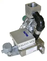
In soil vapor extraction applications a Vapor Control Valve (VCV) is installed on the vacuum side of the vapor extraction blower. The VCV includes a valve body, valve disc, two valve seats, and gear motor. The motor progressively opens and closes the valve in response to input from the three controllers. A solenoid valve provides rapid introduction of dilution air, regardless of valve position.
The VCV regulates input concentrations and provides smooth start up. The VCV simultaneously regulates dilution air and source vapors and accommodates increases and decreases in concentrations. The valve returns to its closed position each time FALCO power is cycled.

After controller set points are adjusted, and the power switch is cycled, startup begins automatically. The VCV first returns to its closed position. Once closed, a switch on the VCV allows the vapor extraction blower to start. A pressure switch senses flow to the oxidizer and allows the electric heaters to preheat the catalyst bed to its reactive temperature. Once up to a preset temperature, the VCV is enabled and vapor introduction begins. The rate of concentration increase, and resulting temperature rise, is controlled by rate alarms on the T2 and T3 controllers. The VCV automatically responds to changes in vapor concentrations by adjusting valve position.
The vapor extraction blower interlocks with the FALCO control panel. Low temperature alarms shut the blower down if catalyst inlet temperature is not maintained. Redundant high temperature alarms shut the blower down if temperatures exceed preset limits. Alarms latch and must be cleared by the operator. A pressure switch interrupts the heater circuit if flow to the oxidizer stops.
In the event of a power failure, the VCV returns to its closed position. When power returns, FALCO automatically executes its startup sequence. Cycled operation is achieved by interlocking control power with a timer.
A heat exchanger bypass valve provides manual regulation of heat recovery efficiency. Vapor input concentrations are automatically regulated by the VCV in response to this heat recovery adjustment. During operation at low concentrations, heat recovery is maximized for energy conservation. During operation at high concentrations heat recovery is reduced to maximize input loading.
Catalytic Oxidizers for Industrial VOC Abatement
The oxidizer controls based on temperatures at the inlet, interior, and exit of the catalyst. Electric heaters raise the catalyst to reactive temperature. Startup and operation is fully automatic. Shutdown results if temperature limits are exceeded.
The oxidizer is sized to accommodate the process stream with sufficient dilution air to reduce concentrations to safe levels for the catalyst. A regenerative blower with variable frequency drive (VFD) accepts process vapors and regulates dilution air to optimize treatment and energy efficiency. FALCO controls regulate inlet concentrations by adjusting VFD speed. Speed is increased during high mass flow of hydrocarbon and decreased during low mass flow or at standby to save energy.
Source vapor with substantial heating value is automatically diluted to breakeven heat content and brought to treatment temperature solely by combustion heat. This breakeven condition is maintained for a broad range of vapor load with heater load near zero. A heat exchanger bypass valve automatically increases heat recovery during low concentration operation and standby, and reduces heat recovery to accommodate high concentrations.
The system is supplied with various data retransmit and capture options for integration with a facilities control system.


